EnterMice
Joysticks & PS/2 Mouse Interface for Enterprise 64 & 128 computer
Contents
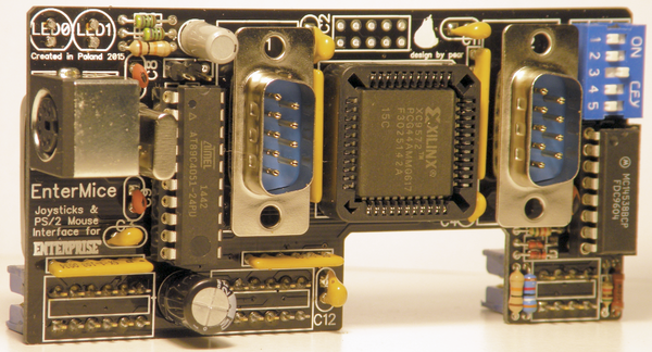
[hide]- 1 Introduction
- 2 List of mouse compatible programs up to date
- 3 General description
- 4 Important
- 5 Connecting to a computer
- 6 Features
- 7 Use of the driver
- 8 Troubleshooting
- 9 Technical specification
- 10 Information for developers
- 11 Manual in other languages
Introduction
This complex interface has been designed for the Enterprise 64/128 series computer.
The achievement is the culmination of six months of work of a multidisciplinary Polish developer known on relevant forums as Pear (at the instigation of the Spanish colleague GFlorez, who with Zozo, from Hungary, where the first testers of the EnterMice).
The main goal of the adapter is to allow the use of cheap and widely available PS/2 mice on the Enterprise computer. In addition, it enables direct connection of two joysticks in Atari standard without additional adapters.
EnterMice is based on solutions used in the BoxSoft mouse interface, which supports the Neos mouse (MSX protocol).
One of the EnterMice operating modes is fully backward compatible with the old BoxSoft mouse interface. An other operating mode converts the mouse movement to joystick pulsations.
A little story about Enterprise and mice
Enhancing the Enterprise 128 with mouse control is not a new and eccentric idea of a geekish retro-computing group, it was already planned by the original EP designers. The problem was that the task was relegated to Aztec Software Ltd, a modest English company that came up with a disappointing job; for two main reasons: first, the product was ugly [1], nothing near the rounded shape of the Enterprise. Secondly, it was not an adequate mouse as it relied on emulated joystick movement. Also at that time Enterprise Computing Ltd. was disappearing.
But the user base in the United Kingdom remained very active in the years following. Little companies were founded by Enterprise enthusiasts. New products were offered: memory expansions, customized cables, games, utilities, Spectrum emulators, an IDE controller, Eprom, motherboard expansions, serial modems and so on.
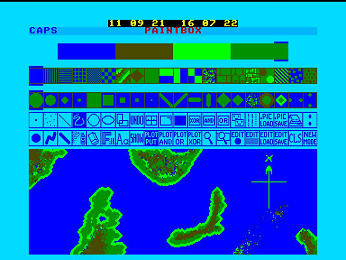
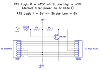
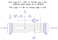
The most prolific company was Boxsoft, founded by developer Tim Box. Boxsoft offered most of the products listed above. Bundled with a paint program called Paintbox [2], they marketed an adapter [3] plus a Neos mouse with a driver included. The Neos, internally [4] a MSX mouse [5], had already been successfully adapted to other 8-bit computers like the Commodore 64.
At that time only a few 8-bit computers had a working mouse with some form of GUI. It was very difficult to sell something new of unknown use and not completely integrated on the computer. Seen from today's perspective, the advantage of navigating operating systems and applications with a mouse is obvious, its convenience being realized instantly when the mouse stops working...
After all, only about a hundred of the Paintbox bundles were sold.
The Paintbox program arrived to Hungary separately. Hungarians bought Enterprise computers knowing that they came from the UK., but not much more. When all the Enterprise 128s were sold, the user base was abandoned as in the country of origin. Once again, new companies surfaced offering new products. Then a company named "A studio" began to manufacture and sell the Boxsoft items, camouflaging them as their own products. One of the programs was a Paintbox version without the mouse option. It still needed the driver, but a crippled version. At the east side of the Iron Curtain nobody ever heard of the Neos mouse.
Later, in Hungary, a serial card expansion [6] for the Enterprise was realized, thanks to the genius of a team of Hungarian developers: Gyula Mészáros for the hardware, and László Haluska (HSOFT) for the software part. HSOFT took the crippled "A studio" mouse driver and modified it to suit the serial interface with a Mouse Systems mouse and later they supplied a built-in driver for the EPDOS 2.x operating system.
This is ancient history, but in recent years with WWW, Internet and globalization, some of the old artefacts Boxsoft+Neos emerged and all pieces of the puzzle began to fit. At last, the old promises (seen on Enterprise Computers Ltd. advertisments) of a real proprietary Enterprise mouse interface turned a reality.
The new EnterMice interface presented here is based on the work of the Boxsoft team, but adapted to recent times, supporting new options. (It is a miracle what Tim Box achieved with only a few logical gates and diodes back then[7]). As for the software, the driver was very well written by D. Rabson, Andrew Fitter and Andrew Richards. With minor modifications, the same driver will be used with the EnterMice adapter.
The principal problem interfacing the Enterprise is that connectors and signals are far from being a joystick-mouse standard. Little edge connectors that can be accidentally plugged upside down, commons pulled to +5v for the buttons when normally zero volt is used, lack of protection of the return of the signal when two or more buttons are pressed, no way to send information or state to the controller, and probably some more issues.
Now what Boxsoft pulled off with common, cheap components, has been redesigned and improved with two programmable chips and other modern components. One of the chips (a Xilinx) is in charge of the pinout and signal conversion to the Atari standard game port connectors. The original Boxsoft interface defined/standardized the first controller port only, that was used to connect the Neos mouse or a standard joystick (but not both at the same time). In the present project two joystick ports have been provided and they don't interfere with the mouse port.
The Neos/MSX mouse is not widely found today so, a PS/2 to MSX conversion adapter has been implemented. It is driven by simple and inexpensive 12 MHz Atmel AT89C4051, able to adapt itself to the frequency of the Z80 processor installed on the Enterprise. With this chip and the proper coding it has inside, the EnterMice can work on a 4 MHz EP or on a supercharged 10 MHz one the same way.
Also, the mouse reading protocol has been expanded following Prodatron and NYYRIKKI's new extended MSX protocol so it can send information about five buttons on a wheel mouse, if present.
List of mouse compatible programs up to date
Multiplay, Iview, Cview, by Istvan-V.[8]+ File, by Zozosoft.[9] Internally.
Paintbox by the mouse driver.[10]
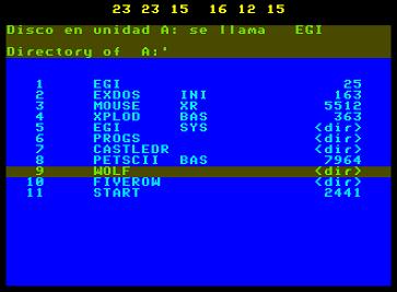
The Enterprise Graphical Interface by the mouse driver.[11]
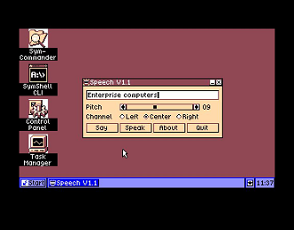
SymbOS internally, on EnterMice mode by hack[12].By Prodatron[13].
Programs in Basic can be made to work with it, by the mouse driver
Old programs that use joystick port 1, with EnterMice in joystick mode.
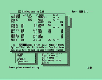
EDC Windows, internally in EnterMice mode and Hsoft driver mode. Use this modified executable: [14]
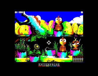
SPEmu128 from geco, the great Spectrum emulator for Enterprise, now is capable of emulate Kempston-mouse adapted games[15] from EnterMice mouse movement. The list of compatible games is growing constantly.[16]
Games list
Pasziansz(Solitaire)[17]. Rom version[18]
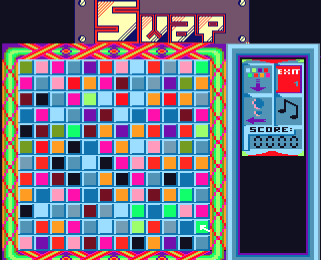
SWAP [19]
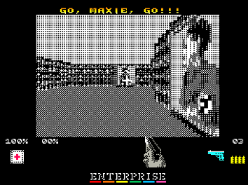
Wolf2004 First person shoot'em up. ZX conversion by Geco[20]
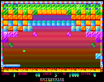
Bricky Prise. Created by Geco, Endi and Szipucsu. Adapted to EnterMice by Isvan-V. [21] and [22]
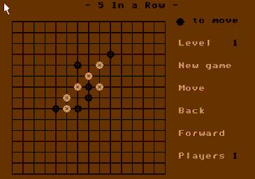
Five in a Row. Strategy game written in Basic. Adapted to EnterMice by Lacika. [23]
Chess Master 2000 Amstrad conversion by Geco.[24]
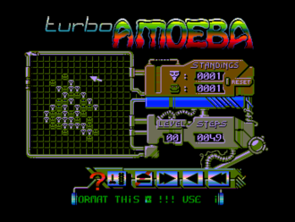
Turbo Ameoba. Adapted to EnterMice by PovySoft.
XEP128 and EP128emu Emulators
Even if you don't have an EnterMice adapter, you can test the feel of managing an emulated Enterprise with a mouse.
Now LGB's XEP128[25] great emulator is able to mimic it accurately from the PC mouse movement. You can even combine it with SPEmu128 to emulate a Spectrum within the emulated Enterprise. The Kempston mouse will obey your PC mouse movements...
Here[26] is an explanation on how to organize the XEP128 emulator to correctly work on a Windows PC.
And here[27] is the explanation for OSX.
Thanks to the works of LGB on his XEP128 emulator, IstvanV has also updated EP128emu for EnterMice emulation. There is a Windows installer for easy installation.
You can download the current version here[28].
General description
Important
Do not connect the interface to the computer when the power is on !
If when you connect the interface your computer does not start up properly or
behaves abnormally, it must be switched off immediately !
Check whether the interface is connected correctly and try again.
Mouse and joysticks can be connected and disconnected while the computer is power on, but this is not recommended. It is safer to perform any connection with the power disconnected.
Warning: Please be sure to read section "Connecting other devices into EnterMice" before you connect the device for which the EnterMice was not designed.
Connecting to a computer
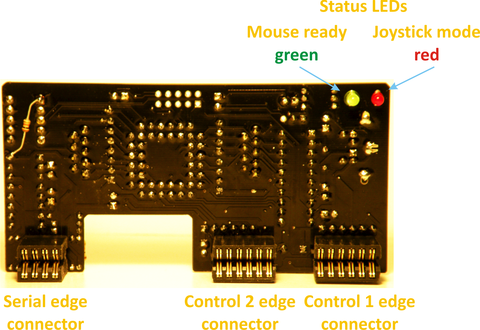
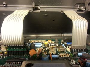
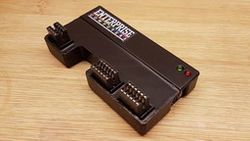
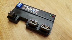
The interface board should be connected at the same time to 3 edge connectors on the back of your Enterprise: Control 1, Control 2 and Serial. You can see that the edge connectors are soldered in a slightly greater angle than 90 degrees. That is intentional to ensure the Entermice fits better the back shape of the Enterprise.
It can be inserted only one way, but the contact pins might not seat centered on the fingers of the edge connectors. If so, the contact might be unstable and the computer and/or the interface may not work.
Properly connected, the interface works right after turning on the power.
After turning on, a self-test is performed, during which both red and green LEDs will flash 3 times (regardless of the state of dip-switch 3).
Once the Entermice is connected to the Enterprise, although it is advisable to plug the mouse before turning on, the interface is provided with a hot-plug feature that recognizes when a mouse is connected, then it is classified and initialised to work.
After successful completion of the mouse initialization, the green LED lights up (if DS3 is ON).
Features
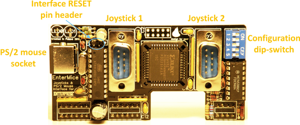
The interface can operate in several modes. To configure it, a five sectional dip-switch is provided.
The configuration settings can be changed during operation of the interface. You do not have to restart your computer.
Below is the description of all possible settings.
| DS1 | DS2 | Work mode |
|---|---|---|
| ON | ON | EnterMice native mouse mode |
| OFF | ON | BoxSoft compatible mouse mode. The two main buttons are swapped. Main now is the right one. |
| OFF | OFF | EnterMice joystick mode (Movement made to the mouse is redirected to the input of Joystick 1, and that port is disabled) |
| ON | OFF | not used (in fact EnterMice as joystick on KB K column) |
Joystick 2 always works the same way, regardless of the interface operating mode being selected.
| DS3 | LED status |
|---|---|
| OFF | LED status disabled |
| ON | LED status enabled |
Joystick emulation mode configuration
| DS4 | Sensitivity |
|---|---|
| OFF | Normal |
| ON | High |
| DS5 | Diagonal correction |
|---|---|
| OFF | Disable |
| ON | Enable |
Diagonal correction improves the precision of joystick simulation on diagonal movements, at the expense of a slight decrease in speed.
Use of the driver
Here [29] you can find the driver.
The following instructions have been took from the original Paintbox manual, corrected and then added the EnterMice new abilities.
The mouse and how to use it in your programs
Using the mouse is not just restricted to machine-code programs, it can be very easily incorporated within almost any Basic program. For this is necessary the use of an EXOS Extension named mouse driver("Mouse.xr").
This device driver will place a pointer on any graphic or text screen and by monitoring the movements of the mouse it will move the pointer around the screen in sync with it. The pointer on text video pages works internally on pixel coordinates, but is drawn only in character boundaries, so the movement can be shown as jerky on short distances.
The Mouse Driver can be instructed to do various commands and functions, for example turning the pointer on and off. There are two ways to communicate with the Mouse Driver, the first is by reading and writing to it and the second is by system variables.
Loading
The Mouse Driver can be loaded by all methods ie; "START" from Basic (if from tape) or load "MOUSE.XR". It can also be loaded from the "WP", from EXDOS or from any other language (check appropriate language for details).
Once loaded it will remain resident until the next hard reset or switch off of the computer.
On previous versions, to properly work it was necessary to initialize it with the EXOS command ":PB". The EGI and Paintbox do this internally.
If you use an outdated version, never execute two times the initialization command, as it can hang the Enterprise. Then ignore the error message it gives. The error code(obtained in Basic with EXTYPE) is 9000+memory page where the driver has been loaded. This was made deliberately by the driver writers.
The actual version auto-initialises itself and doesn't conflicts with older programs that still can use the removed :PB command.
Installing several instances of the driver is not armful, as only the last one will work, but is a waste of memory.
Here is a simple way to detect if the driver has been already loaded in Basic:
100 WHEN EXCEPTION USE DRIVER_LOADING
110      SET 189,4 ! try to set EnterMice control mode. Only possible if the driver has been installed.
120 END WHEN
1000 HANDLER  DRIVER_LOADING
1010      EXT "LOAD MOUSE.XR" ! The file has to be on the current directory, if not, the program will give us another error.
1020      PRINT "Loading the Mouse Driver"
1030      SET 189,4                  ! Here we assume that the driver has been correctly installed.
1040 END HANDLER
It can be made more complex and effective, setting a variable on the handler to signal the not-loaded status, loading the driver on the main program. Then, if the file is not found(probably we are on another path), the error can be parsed on the same or on another handler.
It is a good practice to avoid installing several instances of the Mouse Driver.
Executing ":HELP MOUSE" it will show some version information of the driver and, if a Entermice is plugged it also will show Entermice information.
Communicating with the mouse driver
As stated above there are two ways in which you can communicate with the Mouse Driver. To demonstrate the two methods and their actions, we shall first look at all the commands, functions and variables then demonstrate their use within a program.
Printed commands and functions
The first and most important action is to open the Mouse channel, ie OPEN £?:"MOUSE:" (? being a channel number).
Take in account that a mouse channel is always associated to a video channel where to draw the pointer. Opening a mouse channel without a video channel is not possible and, if the video channel disappears or changes, the mouse routine will detect it, deactivating itself. Remember, the mouse channel will remain opened but ineffective.
To avoid errors, if a video channel must be closed within a program, first close the mouse channel associated to it.
Also, if you STOP your mouse-based Basic program, always type CLOSE £? when typing TEXT, as the Basic Editor automatically closes the graphics video channel.
Commands issued by printing characters to Mouse channel:
| O | Turn pointer on |
|---|---|
| o | Turn pointer off |
| P | Request X & Y position |
Results or status obtained by reading a character from Mouse channel:
Only read after sending "P":
| X | Low byte |
| X | High byte |
| Y | Low byte |
| Y | High byte |
Always readable:
Fire = "1" if main button depressed, "0" if not.
System variables
| Address | Content | Default |
|---|---|---|
| 180 | Video channel, pointer required on | 101 |
| 181 | Position of X,Y co-ordinate on status line | 30 |
| 182 | Status co-ordinate display: 1 on, 0 off | 0 |
| 183 | Colour of pointer {check tech section} | 255 |
| 184 | Low byte of X co-ordinate | |
| 185 | High byte of X co-ordinate. Check demo prog. for co-ordinate conversion. | |
| 186 | Low byte of Y co-ordinate | |
| 187 | High byte of Y co-ordinate | |
| 188 | Status of fire button 0 off, 1 on | |
| 189 | Input device:
0 - Internal Joystick 2 buttons, Space and Enter 1 - Control 1 3 buttons 2 - Control 2 3 buttons 3 - Boxsoft 2 to 5 buttons 4 - EnterMice (default) 2 to 5 buttons 5 - Serial Mouse Sytems 3 buttons 6 - Serial Microsoft 2 buttons >6 - Not implemented |
|
| 190 | Status of secondary button and spare buttons if present, counter of wheel if present.
  Bits 0 to 3 signed nibble of the wheel counter(7 -> -8)
  Bit 4 wheel button
  Bit 6 and 5 spare buttons
  Bit 7 secondary button
      Status of buttons: 0 off, 1 on, if a third button is present it is assigned to bit 4
|
Examples
100 PROGRAM "ms_test.bas"
110 NUMERIC X,V,MAX_Y",X_COUNT,LASTX,LASTY
120 GRAPHICS
130 CALL MOUSE_SETUP
130 OPEN £1:"mouse:" ! Open a channel to the Mouse
140 DO
15D CALL MOUSE_POS
160 LOOK 1:FIRE ! Check the fire button
170 IF FIRE THEN
130 PRINT £1:"o"; ! Turn the pointer off
190 PLOT LASTX,LASTY,X,Y
200 PRINT 1:"O"; ! Turn the pointer on
210 ELSE
I10 PLOT X,Y,
230 END IF
240 LET LASTX=X:LET LASTY=Y
250 LOOP
250 END
270 DEF MOUSE_SETUP
280 LET CHAR_Y=20 ! No. of characters screen high
290 LET X_COUNT=2 ! Pixel calc no
300 SET 180,101 ! Video channel to put mouse pointer on
310 SET 181,30 ! Position of co-ordinates on status line
320 SET 182,1 ! Show co-ordinates
330 SET 183,255" ! Colour of pointer
310 LET MAX_Y=CHAR_Y*36-2 ! Convert char_y to co-ordinates
350 END DEF
-
Note X_COUNT is = to "2" in 2 colour mode "4" in 4 colour mode "8" in 16 colour mode and "16" in 255 colour mode.
All these values double when in lores.
Now you must add the MOUSE_POS routine. It asks the mouse position to the driver. Select one of the two following ways:
Reading the pointer co-ordinates by reading from Mouse channel.
DEF MOUSE_POS
 PRINT £1:"P"
 LOOK £1:XL
 LOOK £1:XH
 LOOK £1:YL
 LOOK £1:YH
 LET X=XL+256*XH
 LET Y=YL+256*YH
END DEF
Reading the pointer co-ordinates from the system variables.
DEF MOUSE_POS
 ASK 184 XL
 ASK 185 XH
 ASK 186 YL
 ASK 187 YH
 LET X1=XL+256*XH
 LET X=X1*X_COUNT
 LET Y=YL+256*YH
 LET Y=Y*2
 LET Y=MAX_Y—Y
END DEF
You can also command the driver to put the pointer where you want:
Setting the Mouse co-ordinates by the system variables.
DEF POS_MOUSE
 LET X=INT(X/X_COUNT)
 LET XL=X-256*INT(X/256)
 LET XH=INT(X/256)
 LET Y=MAX_Y-Y:LET Y=INT(Y/2)
 LET YL=Y-256*INT(Y/256)
 LET LET YH=INT(Y/256)
 SET 184,XL
 SET 185,XH
 SET 186,YL
 SET 187,YH
END DEF
This program is a very simple art program; simply drawing a line to
follow the movement of the mouse when the "Mouse Button" is
pressed. A call is made to MOUSE_POS on line 150, depending on
how you want to read it you should add into the program the
appropriate procedure from the two listed. There is another
procedure listed, that routine enables you to set the position of the
pointer. Simply call it with the desired position in variables X. and Y,
experiment with the different routines, and try and add them into
your own programs, it won't take long to get the feel of them and
after a very short while you will discover just how easy it is to
incorporate the mouse into existing programs and to write mouse
specific programs.
How to use the wheel and the spare buttons in your programs
To manage bits in Enterprise Basic is slow and difficult. The System Variable 190 has a lot of information in it but it's not easy to extract:
100 GRAPHICS
110 SET 180,101
120 SET 183,255
130 OPEN #1:"MOUSE:"
140 ASK 188 A
150 ASK 190 B
160 IF (A) THEN PRINT "Main button"
170 IF (B BAND 128) THEN PRINT "Secondary button"
180 IF (B BAND 16) THEN PRINT "Central button"
190 IF (B BAND 32) THEN PRINT "Fourth button"
200 IF (B BAND 64) THEN PRINT "Fifth button"
210 LET B=(B BAND 15)
220 IF (B BAND 8) THEN LET B=B-16
230 PRINT "Wheel: ";B
240 GOTO 140
You can use this machine code routine inside a Basic program to explode it in five bytes. In addition this MC routine will put to zero the Z_COUNTER every time it's executed:
100 ALLOCATE 42
110 CODE XPLOD=HEX$("18,05,00,00,00,00,00,23,06,
00,0E,BE,F7,10,FE,00,C0,7A,06,04,23,36,00,17,CB,
16,10,F8,23,7A,36,00,ED,6F,57,06,01,0E,BE,F7,10,C9")
120 GRAPHICS
130 OPEN £1:"MOUSE:"
><><><><><><>
520 CALL USR(XPLOD,XPLOD)! We pass the XPLOD address in "hl" register pair
><><><><><><>
930 PRINT PEEK(XPLOD+2)! Secondary mouse button  \
940 PRINT PEEK(XPLOD+3)! Spare button             \
950 PRINT PEEK(XPLOD+4)! Spare button             /  0 idle, 1 pressed
960 PRINT PEEK(XPLOD+5)! Wheel button            /
970 LET B=PEEK(XPLOD+6)! Z_COUNTER(wheel)           two's complement 7 to -8
980 IF B<8 THEN PRINT B
990 IF B>7 THEN PRINT B-16
Here is the disassembly of the machine code routine:
ORG:		jr CODE  ;hl contains the ORG address

BUTTON2:	db 0
BUTTON3:	db 0
BUTTON4:	db 0
BUTTON5:	db 0
Z_COUNT:	db 0

CODE:		inc hl
		ld b,0      ; read
                ld c, 0BEh  ; 190
                rst 030h
                db 10h     ;EXOS 16, Read System Var 190
        	cp 0
         	ret nz     ; if var 190 not found, the driver has not been loaded, return to Basic
         	ld a, d    ;put the obtained value in "a" to be exploded

      		ld b, 4    ; we need a count of 4 for the buttons loop
LOOP:		inc hl
      		ld (hl), 0 ; we don't need old values
         	rla        ; rotate left "a" and put bit 7 on carry
      		rl (hl)	   ; put the carry bit on bit 0 of (hl)
      		djnz LOOP

         	inc hl     ; we still have to extract the wheel count
         	ld a,d     ; recover original 190 variable content on "a"
      		ld (hl), 0 ; we don't need old value
      		rld        ; we are only interested on low nibble of "a"
         	ld d, a	   ; a nibble filled of zeros has come from (hl) to reset the wheel counter
                           ; on low nibble of "a" but leaving the buttons intact on high nibble
      		ld b, 1     ; now we need to write the variable
       		ld c, 0BEh  ; 190
         	rst 030h
         	db 10h     ;EXOS 16, Write System Var 190
         	ret        ;return to Basic
This is an explanation of the procedure to program the wheel:
Low nibble of System variable 190 holds the count of impulses received from the wheel since the last time it was reset. The impulses are positive or negative, the driver adds or subtracts them to the counter, that can hold a value from 7 to -8. The program has to provide a timer routine to check the counter(with XPLOD) every given period. Once checked, the counter is reset to 0(also by the XPLOD routine), and the value found(XPLOD+6) can be used for a task, for example to scroll the screen.
Observe that the secondary mouse button is a "wired" one, and so can also be read directly from the keyboard matrix(with the routine described on the "Reading the joystick interface" section) or easier comparing the value of var 190 with 127(the secondary button is the 7 bit):
ASK 190 SECBUTT
IF SECBUTT>127 THEN GOTO MENU !secondary mouse button pressed!!!
Driver technical information
Executing the HELP command in EXOS you can see the version of the driver in a list that shows all the extensions.
The driver works on both graphic and text modes but it is planned to implement it also on editor modes, executing some action just on the pointer coordinates when a button is being pressed. Once achieved it will be easy to use the mouse for example on the Basic editor, WP or EXDOS.
Values for EXOS variable 183 to change mouse pointer colour
| SETTING | RESULTANT | |
|---|---|---|
| INK | COLOUR | |
| 2 COLOUR MODE | 0 | 0 |
| 255 | 1 | |
| 4 COLOUR MODE | 0 | 0 |
| 240 | 1 | |
| 15 | 2 | |
| 255 | 3 | |
| 16 COLOUR MODE | 0 | 0 |
| 192 | 1 | |
| 12 | 2 | |
| 204 | 3 | |
| 36 | 4 | |
| 228 | 5 | |
| 48 | 6 | |
| 240 | 7 | |
| 3 | 8 | |
| 195 | 9 | |
| 15 | 10 | |
| 207 | 11 | |
| 51 | 12 | |
| 243 | 13 | |
| 63 | 14 | |
| 255 | 15 | |
| 256 COLOUR MODE | 0-255 | 0-255 |
Joystick mode of the EnterMice mouse interface
A mouse plugged on the EnterMice PS/2 port is not just restricted to acting as a mouse, it can be made to simulate a joystick. To activate this mode you must put to OFF both DS1 and DS2 switches. The interface then will convert the mouse movement on the PS/2 connector to joystick movement on Joy 1 port. You don't have to unplug your real joystick from that port as it will be disabled. The mouse will then send movement like that of a joystick, useful to manage old programs or games.
If DS3 is ON, in joystick mode lights up red LED. It's blinking when any direction-contact is shorted.
NOTE: The fire button is the left hand button on the mouse. To make use of the right hand button use the routines shown in the section on the mouse interface.
The joystick ports
The EnterMice mouse interface will not only work as a mouse interface but as an intelligent joystick interface. Any ATARI-Kempston-Amiga style joystick can then be inserted into one of the two 9 pin connectors at the back of the interface board. If the joystick has an autofire option it will work. Mouse and joysticks can stay connected at the same time as they don't interfere one to the others.
Reading the joystick interface
Originally the control ports of the Enterprise only had 1 FIRE button, but now the EnterMice interface provides two more on both ports. Obviously, they will not work on old games, only on new releases or new conversions of games.
All normal methods of reading the two ports work. The only extra code required is to read the extra fire buttons. An example of the code is listed below.
100 PROGRAM "JOYFIRE2.BAS"
110 ALLOCATE 40
120 CODE FIRE=HEX$("7C,F3,D3,B5,DB,B6,FB,A5,28,04,21,00,00,C9,
21,01,00,C9")
130 DO
140 LET FIRE2=USR(FIRE,4)
150 IF FIRE2 THEN PRINT "FIRE I PRESSED"
160 LOOP
This is the disassembly of that little code:
org:                     7c 	          ld a,h  ; h is the row, l is the column. (H*256+L)
                         f3               di
                         d3b5             out (b5h),a
                         dbb6             in a,(b6h)
                         fb               ei
                         a5               and l  ; bit 0 is J column, bit 1 is K column, and bit 2 is L column.
                         2804             jr z,pressed
                         210000           ld hl, 00h
                         c9               ret
pressed:                 210100           ld hl,01h
                         c9               ret
You can read the three Fire buttons of the two joystick ports of EnterMice changing in the Basic line "140 LET FIRE2=USR(FIRE,4)", the "4" by a "1" or a "2".(H=0) For the second port you must use "1281","1282" or "1284".(H=5)
This method also can be utilised to read the two main mouse buttons, that are shared with the FIREs of control 1.
Troubleshooting
Keyboard issue
During the creation of the EnterMice, a fairly serious error in the design of the Enterprise was casually discovered.
It stays totally unnoticed if nothing is connected to the ports Control 1 and Control 2. However, the EnterMice uses them...
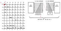
The issue is about interferences on KB0..KB9 ports from keyboard, that are also utilised by the control ports.
If only one key is pressed at the keyboard, then nothing wrong happens (see figure 1).
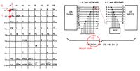
However, if you press two keys in the same column simultaneously, the signal from the selected line will be transferred to the line of the second key as well (figure 2).
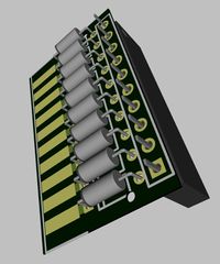
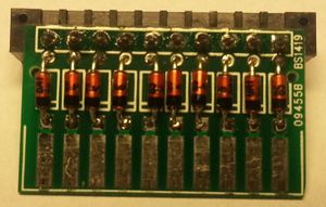
The Enterprise lacks blocking return diodes to separate the rows of the keyboard!
Electrically nothing will happen (the LS145 decoder inside the computer has open collector outputs), but reading from the external ports Control 1 and Control 2 causes errors.
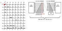
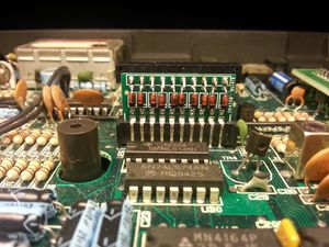
In order to eliminate the cause, diodes should be added to each row of keys on the Enterprise, to avoid that pressing more than one key it can cause "collisions" (figure 3).
Pear has prepared a PCB to fix it. Without this fixer, in order to avoid errors, the keyboard should not be operated while joysticks or mouse are in use.
Microsoft Optical Mouse
The PS/2 Microsoft Optical Mouse is a special case. It should be only connected inserted on its original Microsoft USB to PS/2 converter. It will work with EnterMice if connected before power on, but in this particular case, you can not use the hot-plug feature as it will be not recognised.
EnterMice can be forced to recognise the Microsoft mouse during operation, you only need to momentarily short the RESET pin-header on the interface or press optional RESET button on newer board version (it resets only the interface, not the computer).
Technical specification
Joystick port pinout
| pin | signal |
|---|---|
| 1 | Up |
| 2 | Down |
| 3 | Left |
| 4 | Right |
| 5 | Fire 3 |
| 6 | Fire 1 |
| 7 | +5 V |
| 8 | GND |
| 9 | Fire 2 |
Control Map
| J column (bit 0) | K column (bit 1) | L column (bit 2) | |||||
|---|---|---|---|---|---|---|---|
| JM=0* | JM=1* | JM=0 | JM=1 | JM=0 | JM=1 | ||
| Control 1 | Row 0 Fire | Joy 1 Fire 1 | Mice Left Btn | Mice Left Btn or Joy 1 Fire 2* | Joy 1 Fire 2 | Mice Right Btn or Joy 1 Fire 3* | |
| Row 1 Up | Joy 1 Up | Mice D0 | Mice D0 | spare | spare | spare | |
| Row 2 Down | Joy 1 Down | Mice D1 | Mice D1 | spare | spare | spare | |
| Row 3 Left | Joy 1 Left | Mice D2 | Mice D2 | spare | spare | spare | |
| Row 4 Right | Joy 1 Right | Mice D3 | Mice D3 | spare | spare | spare | |
| Control 2 | Row 5 Fire | Joy 2 Fire 1 | Joy 2 Fire 2 | Joy 2 Fire 3 | |||
| Row 6 Up | Joy 2 Up | spare | spare | spare | spare | ||
| Row 7 Down | Joy 2 Down | spare | spare | spare | spare | ||
| Row 8 Left | Joy 2 Left | spare | spare | spare | spare | ||
| Row 9 Right | Joy 2 Right | spare | spare | spare | spare | ||
* Mouse buttons have higher priority
* JM=0 (DS1 ON)  native EnterMice mouse mode
  JM=1 (DS1 OFF) joystick emulation & BoxSoft compatible mode
Connecting other devices into EnterMice
SEGA Twister
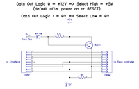
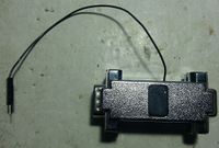
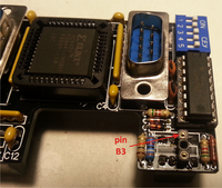
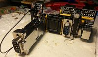
to connect the Sega six-button pad [30]
Sega Six Button Controller Hardware Info
Interface Protocol of SEGA MegaDrive's 6-Button-Controller
| pin | Select = Low | Select = High | Select = pulse-3 |
|---|---|---|---|
| 1 | Up | Up | Button Z |
| 2 | Down | Down | Button Y |
| 3 | GND | Left | Button X |
| 4 | GND | Right | not used |
| 5 | +5V | ||
| 6 | Button A | Button B | not used |
| 7 | Select | ||
| 8 | GND | ||
| 9 | Start | Button C | not used |
Neos mouse
| pin | Function |
|---|---|
| 1 | Up |
| 2 | Down |
| 3 | Left |
| 4 | Right |
| 5 | Not connected |
| 6 | /Strobe - Left Switch |
| 7 | +5V |
| 8 | GND |
| 9 | Button Switch Right |
MSX mouse
| pin | Function |
|---|---|
| 1 | Up |
| 2 | Down |
| 3 | Left |
| 4 | Right |
| 5 | +5V |
| 6 | Button Switch Left |
| 7 | Button Switch Right |
| 8 | Strobe |
| 9 | GND |
USB gadgets
The maximum current available on the PS/2 connector is limited by the efficiency of the Enterprise's internal stabilizers. In practice, the load should not exceed 300mA.
3D housing
First version (DIP switch on the component side)
Second version (DIP switch on the side of the edge connectors)
Information for developers
EnterMice timings
The firmware of EnterMice is optimized for the cyclic reading with 50 Hz frequency (video IRQ).
| Default reading cycle | 20 ms |
| Waiting time to perform self-test the PS/2 mouse (timeout) | ca. 2000 ms |
| Time of collecting the PS/2 mouse data | max. 12 ms |
| Time from change state of RTS signal to issue data (nibble) for reading | 25 μs |
| Standby time for the next reading (counting from data issue) | 14 μs |
| Time from read the last nibble of data to reset the nibble counter (timeout)* | 1500 μs |
| Default mouse polling time in joystick emulation mode | 30 ms |
| Mouse polling time in joystick emulation mode when mouse doesn't move (minimize polling delay) | 12,5 ms |
* After this time starts another mouse data polling.
Data buffer
Data buffer in EnterMice has a size of 16 bytes.
Currently is used only a half. The remainder may be used in the future.
| Bits | High nibble | Low nibble | Content | |||||||||
|---|---|---|---|---|---|---|---|---|---|---|---|---|
| Byte | 7 | 6 | 5 | 4 | 3 | 2 | 1 | 0 | ||||
| 0 | X value | signed int (positive is moved left) | BoxSoft protocol | |||||||||
| 1 | Y value | signed int (positive is moved up) | ||||||||||
| 2 | 0 | 0 | 0 | 1 1) | 0 | Btn5 | Btn4 | Btn3 | Protocol identification & buttons 3,4,5 state (1=pressed) | Extended MSX protocol | ||
| 3 | Horizontal wheel 2) | Z value | signed int (positive is wheel moved up) | |||||||||
| 4 | ExCnt 3) | Mouse ID | Extra bytes available to read (include this) & PS/2 mouse ID | EnterMice extension protocol | ||||||||
| 5 | Hw ver. mj. | Hw ver. mn. | Hardware version (major.minor) | |||||||||
| 6 | Fw ver. mj. | Fw ver. mn. | Firmware version (major.minor) | |||||||||
| 7 | Device ID | EnterMice ID is 5Dh | ||||||||||
1) If the device only supports the BoxSoft protocol, the fifth nibble is always equal to 0000.
2) Not implemented yet, now all 8 bits represents a Z value (Vertical wheel).
3) If the device doesn't support the EnterMice protocol, the ninth nibble is always equal to 0000.
You do not need to read all the data from the buffer.
Reading can be interrupted at any time. There will be the timeout and interface performs another read data from mice, then once again be ready to send data.
Last state of RTS signal also not matter. EnterMice reacts to the change state, not on the signal level.
Mouse reading
; Here begin the Neos mouse reading


ld hl,X_REL
; first byte


ld a,2
; put RTS low, the contrary to normal MSX


out (0B7h),a


ld b,3
; long delay. Stock was 8


call WAIT


call READ_4BIT
; read four higher bits


rld
; push them in (HL)


xor a
; put RTS high


out (0B7h),a


ld b,2
; short delay. Stock was 5


call WAIT


call READ_4BIT
; read four lower bits


rld
; push them in (HL)


ld hl,Y_REL
; second byte


ld a,2
; put RTS low


out (0B7h),a


ld b,2
; short delay. Stock was 5


call WAIT


call READ_4BIT
; read four higher bits


rld
; push them in (HL)


xor a
; put RTS high


out (0B7h),a


ld b,2
; short delay. Stock was 5


call WAIT


call READ_4BIT
; read four lower bits


rld
; push them in (HL)


;<======Here will be added the future Wheel and three spare buttons reading. SECOND TENTATIVE


ld hl,SW_Z_STATUS


ld a,2
; put RTS low


out (0B7h),a


ld b,2
; short delay. Stock was 5


call WAIT


call READ_4BIT
; read four higher bits


and 15


cp 1
; IF THIS NIBBLE=0001 THEN THE MOUSE IS IN EXTENDED PROTOCOL


jr z,CONTINUE_READ


xor a
; we must leave RTS high for the next mouse reading cycle


out (0B7h),a
;IGNORE THAT NIBBLE


ld (hl),0
; we don't need old values


jr STOP_READ


CONTINUE_READ:


xor a
; put RTS high


out (0B7h),a


ld b,2
; short delay. Stock was 5


call WAIT


call READ_4BIT
; read four higher bits, the three lower bits are the buttons. They come ready to store


push af
; push them in stack. they are in the lower nibble.


ld a,(hl)
;


push af
;save the Z counter for later.


ld a,2
; put RTS low


out (0B7h),a


ld b,2
; short delay. Stock was 5


call WAIT


call READ_4BIT
; read four bits


rld
;we need z displacement in 8 bit


xor a
; put RTS high for the next mouse reading cycle


out (0B7h),a


ld b,2
; short delay. Stock was 5


call WAIT


call READ_4BIT
; read four lower bits. Z displacement


rld
; push them in (HL)	;NOW WE HAVE Z displacement in (hl)


pop af
; restored Z counter to "a", but we have garbage on high nibble


and 00Fh


bit 3,a


jr z,SIGN_DONE


or 0F0h


SIGN_DONE:

; now we have the sign extended to 8 bits on "a"


add a,(hl)


cp 128
; positive or negative?


jr c,POSITIVE


cp 248
; lower than -8?


jr nc,FINISHED
;


ld a,248
; -8 is the bottom


jr FINISHED


POSITIVE:


cp 8
; higher than 7?


jr c,FINISHED


ld a,7
; 7 is the top


FINISHED:

; the excess of 7 or -8 has been wiped


ld c,a
; save Z addition on c


pop af
; retrieve the buttons status. They are now on first nibble of a


rld
; buttons stored


ld a,c
; we only need the first nibble of Z counter addition


rld
; the spare buttons status and the Z counter are now in SW_Z_STATUS


STOP_READ:


xor a
; recall buttons on row 0


out (0B5h),a


in a,(0B6h)
; read Mouse buttons


and 7
; mask


xor 7
; flip them all as on Enterprise a pressed key is 1 and released 0


rl (hl)
; Get ready the bit 7 of "hl" register pair. Inside is SW_Z_STATUS, variable number 190


srl a
; This is the very FIRST "srl a". The button status is now in the carry flag


; secondary button of Boxsoft is read on J column. Primary button of EnterMice is read on K column


push af


ld a,(INPUT_DEVICE)


cp 3
; Boxsoft interface mode buttons


jr nz,L_BUTTON


pop af
; We need the value of "a" and "f" registers. Carry flag still stores the value of secondary button


rr (hl)
; secondary button goes to bit 7 of SW_Z_STATUS, variable number 190


srl a
; Primary button of Boxsoft is on J column. This is the second "srl a"


JR MAIN_BUTTON


L_BUTTON:

; EnterMice interface mode buttons


pop af
; retrieve the value of register "a". "f" is disposable, soon we will load the button on carry flag


push af
; I still will need later the register "a" value


srl a
; two "srl a" because the secondary button of EnterMice is read on L column


srl a
; the proper button status is now in the carry flag


rr (hl)
; secondary button goes to bit 7 of SW_Z_STATUS, variable number 190


pop af
; retrieve the value of register "a" just after the FIRST "srl a"


MAIN_BUTTON:


and 1


ld (FIRE_STATUS),a
; EXOS Variable 188. K column if Boxsoft or L column if EnterMice


call sub_C3A6
; this is the "corrections and drawing" routine where the "velocity" 1.1 modification was made


ld a,(X_REL)


ld c,a


ld a,(Y_REL)


or c


ret


XXXXXXXXXXXXXX
XXXXXXXXXXXXXXXXXXXX
XXXXXXXXXXXXXX


WAIT:


nop


nop


nop


dec b


jr nz,WAIT


ret


XXXXXXXXXXXXXX
XXXXXXXXXXXXXXXXXXXX
XXXXXXXXXXXXXX


READ_4BIT:

; I split the routine in two to not put more processor time


ld b,4


ld d,0


ld a,(INPUT_DEVICE)


cp 3


jr z,J_COLUMN


K_COLUMN:


ld a,b


;inc c
; this is not necessary


out (0B5h),a


in a,(0B6h)


;ld c,a
; this is not necessary


rra
; data read from K column


rra


rl d


djnz K_COLUMN


jr CONTINUE


J_COLUMN:


ld a,b


;inc c
; this is not necessary


out (0B5h),a


in a,(0B6h)


;ld c,a
; this is not necessary


rra
; data read from J column


rl d


djnz J_COLUMN


CONTINUE:


ld a,d


ret
Minimum EnterMice reading routine, thanks to Bruce Tanner
This 79 bytes routine is strictly MSX protocol, only reads movement plus the two main buttons. It is intended for easy conversions or adaptations of old programs or games. It must be driven by a 50Hz interrupt, and assumes that X_REL and Y_REL are contiguous in memory.
ld hl, X_REL
;first byte, X displacement since last lecture


ld b,3
;long delay


call READ_8BIT


inc	hl
;Y_REL


ld	b,2
;short delay


call READ_8BIT
;leaves B=0


xor a


out (0B5h), a


in a, (0B6h)


and 6


xor 6


srl a
; here the status of J column is on carry, but is discarded


srl a


rl b
; K column is saved in b


ld (SECBUTT_STATUS), a
; L column is the Right Mouse Button


ld a,b


ld (MAINBUTT_STATUS), a
; K column is the Left Mouse Button


ld a, (HL)
;Y-rel


dec hl
;X-REL


or (hl)
;If a=0, no movement


ret


 XXXXXXXXXXXXXXXX
XXXXXXXXXXXXXXXXXXXXXXXX
XXXXXXXXXXXXXXXXXXX


 WAIT:


nop


nop


nop


dec	b


jr	nz, WAIT


ret


 XXXXXXXXXXXXXXXX
XXXXXXXXXXXXXXXXXXXXXXXX
XXXXXXXXXXXXXXXXXXX


 READ_8BIT:
ld a,2
;RTS low


out (0B7h), a


call WAIT_READ_4BIT
; read four higher bits


xor a
;RTS high


out (0B7h), a


ld b, 2
;short delay


 WAIT_READ_4BIT:
call	WAIT
;leaves B=0


 READ_4BIT:


ld	d, b
;d=0


ld	b, 4


 READ_LOOP:


ld	a, b


out	(0B5h),	a


in	a, (0B6h)


rra
;data is read from K column


rra


rl	d


djnz READ_LOOP


ld	a, d


rld


ret
A still more condensed Mouse+all buttons+wheel reading routine, thanks by IstvanV
This routine even checks for VSYNC(50Hz)itself.
 ;read EnterMice mouse input, returns:


 ;  Z flag = input is valid


 ;  H = X_REL


 ;  L = Y_REL


 ;  A bits 0 and 1 = buttons 1 and 2


 ;  D bits 0 to 2 = buttons 3 to 5


 ;  E bits 0 to 3 = mouse wheel Y


 MOUSEINPUT:


DI


 VSYNCWAIT1:
IN A,(0B4H)


AND 10H


JR Z,VSYNCWAIT1


 VSYNCWAIT2:
IN A,(0B4H)


AND 10H


JR NZ,VSYNCWAIT2


LD C,4


 READ_LOOP_1:
LD H,L


LD L,D


LD D,E


LD E,01H


LD A,02H
;RTS low


 READ_LOOP_2:
OUT (0B7H),A


LD B,17
;25.6 us at 10 MHz without wait states


 M_WAIT_LOOP:
DJNZ M_WAIT_LOOP


LD B,4


 READ_LOOP_3:
LD A,B


OUT (0B5H),A


IN A,(0B6H)


RRA
;data is read from K column


RRA


RL E


DJNZ READ_LOOP_3


LD A,B
;RTS high


JR NC,READ_LOOP_2


DEC C


JR NZ,READ_LOOP_1


OUT (0B5H),A
;A = 0


IN A,(0B6H)


CPL


AND 06H
;bit 0 = left button,


RRA
;bit 1 = right button


BIT 7,D
;bits 5 to 7 of button state must be 0


RET
;IRQ disabled, Z = mouse detected
Mouse buttons reading without executing the routine
EnterMice manages main buttons (wired ones) in a different manner than Boxsoft+Neos. On the original interface you always can read the two buttons like you do with the joysticks fire keys, writing a zero or a five to the B5h Z80 port and then reading the returned value on the B6h port. This independently of reading or not the main mouse movement routine.
Due to the software nature of the PS/2 protocol, this can't be done directly on EnterMice, but the buttons alone can be requested easily by changing RTS state (just at least 2 μs and then can again high just before writing zero to B5h port). Then, after 1,5 ms EnterMice will start parsing PS/2 (that lasting in worst case 12 ms) and then putting on B6h port the correct values for the buttons.
Example:
ld a,2


out (0B7h),a
;RTS is put low


CODE


CODE


CODE


CODE


CODE


CODE


CODE


xor a


out (0B7h),a
;RTS is put high again


out (0B5h),a
;Keyboard row 0 is requested


in a, (0B6h)
;The two mouse buttons are read on bits 1 and 2
