|
 
| |
|
See the Links panel on the left.
Now supports Windows
NT/2000/XP/2003!
The PC parallel port provides the lowest cost way to interface to
data acquisition hardware. It also provides the lowest raw performance way to
acquire analog data, when implemented in its simplest form. Practical sample rates
are limited to about 1000 samples per second (1K samples/s), also called a 1 KHz sample
rate -- if sampling and hardware control are done in high-level software, such as Visual
Basic®. None-the-less, if your aspirations are limited, a parallel port A/D can
work very well.
A Simple Start
I have found a simple A/D that connects to the PC parallel port that costs less than
$30 in kit form. It can be purchased from Marlin P. Jones & Assoc., Inc.
Look for the PC Analog Data Sampler kit 8412-KT (earlier designated
K-112) at www.mpja.com. BTW, to save a little
money, order from their printed catalog, not online! The printed catalog lists the
kit at $23.21, while the online catalog lists it at $29.95! If you are in
the UK, this hardware is available
here.
This A/D comes with both DOS and Windows software, including both executable programs
and source code. However, the source code has some serious limitations.
First, the source code was written for Windows 3.x; thus it must be ported to the
32-bit compilers that we might want to use. The VB code example uses vbASM.DLL (from
www.softcircuits.com), a 16-bit DLL. To use a 32-bit version of VB, one
would have to use a comparable 32-bit DLL (and a Windows Kernel-Mode device
driver for Windows NT variants).
Also, the designer of this kit (he also wrote the code examples that are furnished with
it) made a "hardware design decision" that has an impact on how it works -- a
decision that is not obvious. The actual design causes the A/D to enter a new
acquisition cycle as soon as data from the previous cycle have been read. This can
speed operation and is a useful feature, but... the consequence is that if you want to
read the A/D at a specific instant in time, you must read it twice. The first
read clears data from the last cycle (data that were acquired when last read). The
second read is what you actually need, the data that were acquired as a result of its
immediate predecessor. This fact is not well described, and is not accounted for in
the furnished example code. In addition, the kit designer used do-nothing loops to
time data acquisition cycles. This approach works under DOS or Windows 3.x, where
preemptive multitasking is not in effect. However, 32-bit versions of Windows use
preemptive multitasking, rendering this technique less desirable.
The First Step
Where to start? Well, first we must decide how to read and write
to the I/O ports that are assigned to the PC printer port. Fortunately, I had
already written a simple DLL that permits this under Windows 95/98. Visual Basic has
no native method for this, so I used Delphi 2.0 to write a 32-bit DLL for this purpose.
Readers of my book, Visual
Basic Programmer's Guide to Serial Communications, will find get a copy
of this DLL, with a description of how I use it in the context of doing non-standard
manipulation and monitoring of the serial port UART.
One of my goals on this project was to provide a method that
was as easy to use as possible, and one that executed all of the
low-level handling of the parallel port for the user. As a result, I decided that
the best approach was to write an ActiveX control (OCX) that provided a set of properties,
methods, and events to represent the most common uses of the A/D, while allowing the user
to add any features that I hadn't included in fairly simple VB (or VBA) code. This
allowed me to create a completely functional interface to the hardware, while keeping
control of the source code, and hiding complexities (such as those that I described above)
from the user. It is not my intent that this OCX offer all of the features that a
commercial product might. Rather, it is designed to show what might be done , and to
illustrate some of the limitations of high-level programming and inexpensive hardware.
OCX Design Goals
 | Allow acquisition of a single data point, or continuous acquisition for a
reasonable amount of time, at selected sample rates. |
 | Implement optional "Digital Storage Scope" functions, such as
triggering on positive or negative slopes, and a selectable trigger level. |
 | Provide optional user interface features for the "Digital Storage
Scope." These include scrolling, zooming in and out on a captured waveform, and
an "LED" type indicator to indicate acquisition state. |
 | Provide an optional graticule, and trigger level display. Display
the sample size and sample rate that have been selected. |
 | "Digital Storage Scope" user interface elements may be visible
when used, but need not be displayed if not used. |
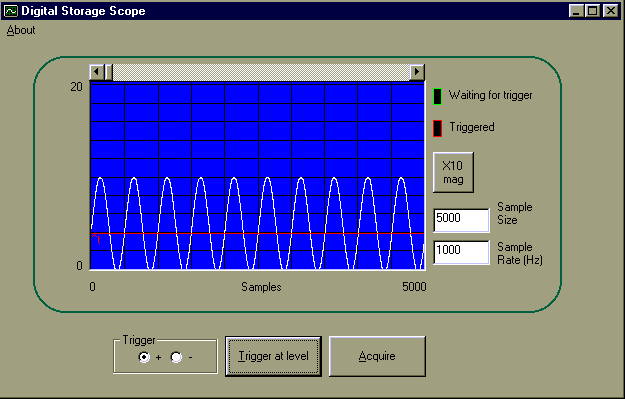
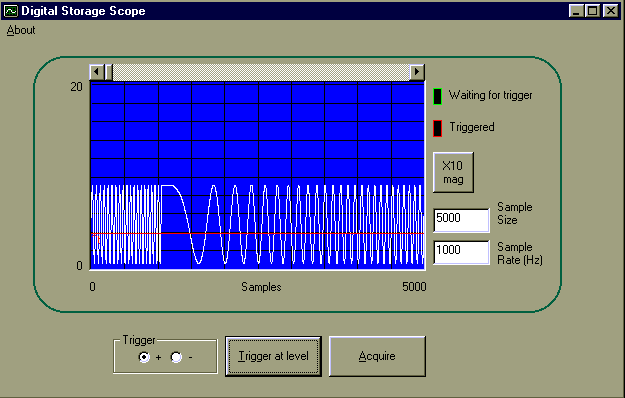
The result of these goals is shown in the figures below, where the
"Digital Storage Scope" functions are shown in use. The actual OCX visual
interface is outlined by the green rounded rectangle. Radio buttons and command
buttons outside the green rectangle are were implemented in the supporting VB program,
though they might have as easily been built into the OCX.

Digital Scope Image 1

Digital Scope Image 2
Using the OCX (Properties, Events, and Methods)
Here is the VB code that was used to implement the Digital Storage Scope that is
displayed in Images 1 and 2.
Option Explicit
Private Sub About_Click()
DacOCX1.About
End Sub
Private Sub cmdAcquire_Click()
DacOCX1.FillBuffer
End Sub
Private Sub cmdTrigger_Click()
DacOCX1.WaitForTrigger
End Sub
Private Sub Form_Load()
optTrig(0) = True
'Set the Radio button to trigger on a positive slope
DacOCX1.BaseAddress = &H378
'LPT1
DacOCX1.DisplayEnabled = True
'Show the digital
scope
DacOCX1.EnableGraticle = True
'Display the graticule -- spelling varies
DacOCX1.SampleRate = High_1000 '1 KHz
DacOCX1.SampleSize = 5000
'5000 samples
DacOCX1.ShowTrigger = True
'Display the selected trigger level
DacOCX1.TriggerLevel = 20
'Trigger at 1.56 V
End Sub
Private Sub optTrig_Click(Index As Integer)
If Index = 0 Then
DacOCX1.TriggerSlopePlus = True
Else
DacOCX1.TriggerSlopePlus = False
End If
End Sub
Now, this simply isn't very complicated! In fact, the
Form_Load code could have been simplified by setting these properties in the DacOCX1
Properties window at design time. All of the details for handling the hardware, and
for providing most of the user interface, are done in the DacOCX. Use this link to
view the DacOCX properties, methods, and events.
Signal Conditioning
This A/D has no built-in signal conditioning, except for a simple range switch that is
used to select input voltage ranges of 0-2V or 0-20V. Also, it provides no isolation
between analog input and the PC. Any isolation or other signal conditioning that may
be required must be done externally. Here is a good tutorial on Signal Conditioning www.cyberresearch.com/tech/DADesign.html.
Good articles also are available from various magazines
online.
Data logging and other applications
This, and even other more complex parallel port A/Ds, provide limited performance.
The 1 KHz maximum sample rate that the DacOCX offers is the maximum that such a
simple system can offer (at this writing). Even so, continuous data acquisition at
this speed can be adversely affected by multitasking other software, or even simple
operations within our own application, such as writing or reading disk data.
However, this simple A/D shines when it comes to data logging. Low-speed data
acquisition needs, such as temperature monitoring, volume measurements in storage tanks,
etc., may be done without concern for the effect of multitasking or other influences.
The Alarm example that may be downloaded from the Download page provides one simple
example of monitoring. Others can be developed using the DacOCX with ease.
|
|
![]()